
The Workshops
- Thread starter 8BitCosmonaut
- Start date
What's the difference between like a musket and go brrrt tho?
With a musket, you fire once, reload, fire again, etc.
So it sounds like "Bang! Interval. Bang! Interval. Bang! Interval. Etc etc", in contrast with a machine gun.
What's the difference between like a musket and go brrrt tho?
Would that be the Gau-8?
Would that be the Gau-8?
Mars Pathfinder
«★★» CMDR «★★» // PT // FartFinder
Deja Vu
Hot Stuff
Space Glider
Swingin' on a Star
Atlas
Christmas Event Category Winner
For the purposes of this, assume that brrrrrrt is supposed to sound like a machine gun (spoiler, it doesn't).
With a musket, you fire once, reload, fire again, etc.
So it sounds like "Bang! Interval. Bang! Interval. Bang! Interval. Etc etc", in contrast with a machine gun.
With a musket, you fire once, reload, fire again, etc.
So it sounds like "Bang! Interval. Bang! Interval. Bang! Interval. Etc etc", in contrast with a machine gun.
Horus Lupercal
Primarch - Warmaster
Deja Vu
Swingin' on a Star
ET phone home
Floater
Copycat
Professor
Cue Horus rant about the A-10 gun not sounding anything like that.
Imagine the sound the worlds most enormous dragon would make if it was trying to gargle the worlds largest running buzzsaw whilst spitting out supersonic milk bottle sized explosive ammunition at several thousand rounds per minute.
Astatium_209
Alliance’s Executor // Unstable and Toxic
Deja Vu
Hot Stuff
Space Glider
Swingin' on a Star
Copycat
Moon Maker
Atlas
MOTY 2021
Allow me to hijack this thread for some of my future electronics projects ; ]
I've been playing around with the pi pico recently, and I decided that I could probably use the programmable IOs to read an sbus protocol from a receiver instead of reading PWM signals with interrupts. Perhaps (probably, in fact) there exists a better way to do this than what I am showing here, it was interesting none-the-less.
Below is the C code, written using theC/C++ SDKprovided by Raspberry.
The programmable IOs are programmed using a language that's basically assembly if I understand correctly. Here's what I came up with. This is pretty ugly, and maybe could be done better...? But if it aint broke, don't fix it, and I barely know what I'm doing.
And here's the output. Sbus can transmit up to 16 channels, but my transmitter only has 8.
1036, 1060, 1516, 1041, 1047, 940, 1847, 457
The values are in the range of 192 - 1792.
The connection diagram is super simple, since sbus is a single-wire protocol.
I spent about a week on this, maybe not worth the time. Maybe the uart can be configured somehow to read the signal. I'm sure PIOs will be useful for other stuff.
I've been playing around with the pi pico recently, and I decided that I could probably use the programmable IOs to read an sbus protocol from a receiver instead of reading PWM signals with interrupts. Perhaps (probably, in fact) there exists a better way to do this than what I am showing here, it was interesting none-the-less.
Below is the C code, written using theC/C++ SDKprovided by Raspberry.
#include <stdio.h>
#include "pico/stdlib.h"
#include "hardware/pio.h"
#include "hardware/clocks.h"
#include "sbus.pio.h"
#define RX_PIN 0
#define SBUS_BAUD 100000
uint16_t input[9];
volatile uint32_t buffer[8];
uint16_t flags;
PIO pio;
uint sm;
void sbus_pull(){
for (int i = 0; i < 8; i++){
buffer = pio_sm_get(pio, sm);
}
pio_interrupt_clear(pio, sm);
}
void convert_inputs(){
uint ii;
ii = 0;
for (int j = 0; j < 3; j++){
input[ii] = buffer[j+2] >> j & 2047;
input[ii+1] = buffer[j+2] >> 11+j & 2047;
input[ii+2] = buffer[j+2] >> 22+j | buffer[j+3] << (10-j) & 2047;
ii += 3;
}
flags = buffer[7] >> 16 & 65535;
}
int main(){
stdio_init_all();
pio = pio0;
sm = pio_claim_unused_sm(pio, true);
uint offset = pio_add_program(pio, &sbus_program);
pio_sm_config c = sbus_program_get_default_config(offset);
sm_config_set_in_pins(&c, RX_PIN);
sm_config_set_in_shift(&c, true, true, 32);
sm_config_set_sideset_pins(&c, RX_PIN + 1);
sm_config_set_fifo_join(&c, PIO_FIFO_JOIN_RX);
pio_gpio_init(pio, RX_PIN);
pio_gpio_init(pio, RX_PIN + 1);
pio_sm_set_consecutive_pindirs(pio, sm, RX_PIN, 1, false);
pio_sm_set_consecutive_pindirs(pio, sm, RX_PIN + 1, 1, true);
float div = (float)clock_get_hz(clk_sys) / (4 * SBUS_BAUD);
sm_config_set_clkdiv(&c, div);
pio_set_irq0_source_enabled(pio, pis_interrupt0, true);
irq_set_exclusive_handler(PIO0_IRQ_0, sbus_pull);
irq_set_enabled(PIO0_IRQ_0, true);
pio_sm_init(pio, sm, offset, &c);
pio_sm_set_enabled(pio, sm, true);
while (1){
convert_inputs();
printf("%u, %u, %u, %u, %u, %u, %u, %u\n", input[0],input[1],input[2],input[3],input[4],input[5],input[6],input[7]);
}
return 0;
}
.program sbus
.wrap_target
wait 1 pin 0 [31]
set x, 24 [15]
byteloop:
nop [3]
in pins, 1 [3]
in pins, 1 [3]
in pins, 1 [3]
in pins, 1 [3]
in pins, 1 [3]
in pins, 1 [3]
in pins, 1 [3]
in pins, 1 [3]
jmp x-- byteloop [11]
irq set 0
in null, 31
in null, 31
in null, 2
.wrap
.wrap_target
wait 1 pin 0 [31]
set x, 24 [15]
byteloop:
nop [3]
in pins, 1 [3]
in pins, 1 [3]
in pins, 1 [3]
in pins, 1 [3]
in pins, 1 [3]
in pins, 1 [3]
in pins, 1 [3]
in pins, 1 [3]
jmp x-- byteloop [11]
irq set 0
in null, 31
in null, 31
in null, 2
.wrap
1036, 1060, 1516, 1041, 1047, 940, 1847, 457
The values are in the range of 192 - 1792.
The connection diagram is super simple, since sbus is a single-wire protocol.
I spent about a week on this, maybe not worth the time. Maybe the uart can be configured somehow to read the signal. I'm sure PIOs will be useful for other stuff.
Astatium_209
Alliance’s Executor // Unstable and Toxic
Deja Vu
Hot Stuff
Space Glider
Swingin' on a Star
Copycat
Moon Maker
Atlas
MOTY 2021
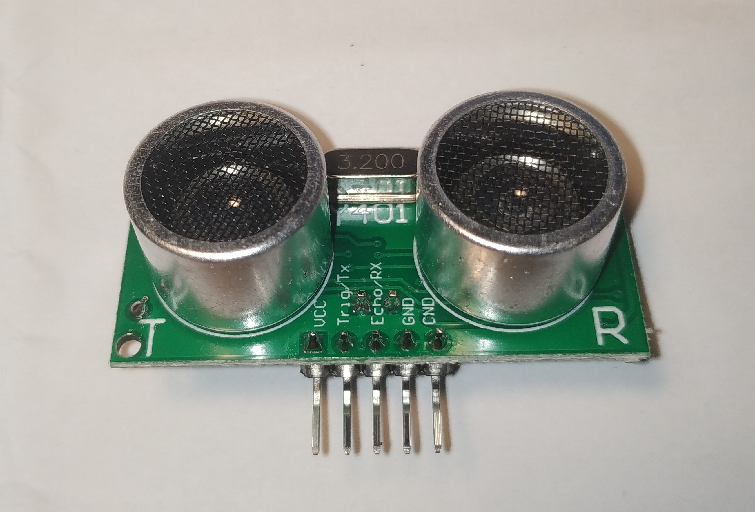
Why on earth did the person who designed this put the CND pin next to the GND pin! Head scratching guaranteed.
Edit:
Jesus Christ, why the heck can I hear it? Have I broken it?
Edit2:
I've tested all of my ultrasound sensors, and they're operating at a resonant frequency of 95 Hz.
Oddly enough, they work, kinda.
Edit3: So I just checked the internet, and apparently that's just another ground pin. That's mildly reassuring, but why are all my ultrasound sensors buzzing?
Last edited:
Why on earth did the person who designed this put the CND pin next to the GND pin! Head scratching guaranteed.
View attachment 95029
Edit:
Jesus Christ, why the heck can I hear it? Have I broken it?
Edit2:
I've tested all of my ultrasound sensors, and they're operating at a resonant frequency of 95 Hz.
Oddly enough, they work, kinda.
Edit3: So I just checked the internet, and apparently that's just another ground pin. That's mildly reassuring, but why are all my ultrasound sensors buzzing?
Astatium_209
Alliance’s Executor // Unstable and Toxic
Deja Vu
Hot Stuff
Space Glider
Swingin' on a Star
Copycat
Moon Maker
Atlas
MOTY 2021
Oooh, is that the echolocation thing?
Yeah, it's a US-100. I bought it because it has uart communication as well as the classical HC-SRF04 communication protocol, although I haven't gotten it to work. I'm kinda giving up on it now, I'm going to try to rely solely on an BMP280 for alititude estimation. The ultrasonic sensor would only work for like 5 meters or so...
Astatium_209
Alliance’s Executor // Unstable and Toxic
Deja Vu
Hot Stuff
Space Glider
Swingin' on a Star
Copycat
Moon Maker
Atlas
MOTY 2021
You can get crazy accurate with barometers if you calibrated before the flight recently from a reference
My dad made a lego technic robot using these and a pi (or arduino, I don't remember) to pathfind. Was really cool
Whilst we're at what our dads built... my dad once built a Stirling engine out of Merkur. I never saw it run though, and it's been disassembled for a long time.
Astatium_209
Alliance’s Executor // Unstable and Toxic
Deja Vu
Hot Stuff
Space Glider
Swingin' on a Star
Copycat
Moon Maker
Atlas
MOTY 2021
The heck?
DSHOT on Mbed | Mbed
This from the DSHOT protocol for ESCs. Why on earth would they represent 1s and 0s like this?
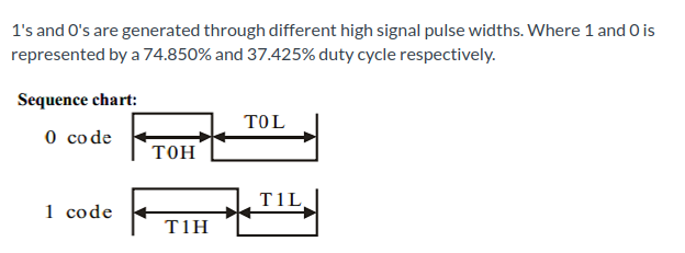
This is going to be a pain in the bum to implement with the PIOs on the raspberry pi pico for my drone project.
I'm still going to do it, because Bluejay doesn't seem to support PWM signals (I've tested it), and unlike BlHeli_S, it can play nice tunes on the motors.
DSHOT on Mbed | Mbed
This from the DSHOT protocol for ESCs. Why on earth would they represent 1s and 0s like this?
This is going to be a pain in the bum to implement with the PIOs on the raspberry pi pico for my drone project.
I'm still going to do it, because Bluejay doesn't seem to support PWM signals (I've tested it), and unlike BlHeli_S, it can play nice tunes on the motors.
Astatium_209
Alliance’s Executor // Unstable and Toxic
Deja Vu
Hot Stuff
Space Glider
Swingin' on a Star
Copycat
Moon Maker
Atlas
MOTY 2021
Well, after a lot of elbow grease, I've got the DSHOT protocol to work. This article was instrumental to my success.
In the end, it was actually quite simple to implement. Or rather, the code required is simple, debugging it was hard.
Here's the PIO assembly code:
If anyone wants me to explain what each line does, I'll do it, but otherwise I won't waste space, haha. There's also some setup code in the main c file, but it's similar to what I did with SBUS in one of my previous posts on this thread.
Interestingly, Dshot150, the 150Kbaud version of the protocol, doesn't work with my Chaos 20A ESCs, while the faster Dshot300 300Kbaud one works just fine.
Welp, if I'm ever going to need to increase my PID loop frequency, I can go to like 16Khz before I'm limited by the transmission speed, but I think my 450mm quad will do just fine with 500hz.
This has no real benefit for me, except for the fact that I can now make the motors play a melody on startup, which automatically makes it like 10x cooler. So, so worth it!
In the end, it was actually quite simple to implement. Or rather, the code required is simple, debugging it was hard.
Here's the PIO assembly code:
.program dshot
; sm set to 2.4MHz for a 300Khz baud, so 1 bit == 8 cycles
.wrap_target
pull block
out null, 16
set x, 15
bitloop:
set pins, 1 [2]
out pins, 1 [2]
set pins, 0
jmp x-- bitloop
.wrap
; sm set to 2.4MHz for a 300Khz baud, so 1 bit == 8 cycles
.wrap_target
pull block
out null, 16
set x, 15
bitloop:
set pins, 1 [2]
out pins, 1 [2]
set pins, 0
jmp x-- bitloop
.wrap
Interestingly, Dshot150, the 150Kbaud version of the protocol, doesn't work with my Chaos 20A ESCs, while the faster Dshot300 300Kbaud one works just fine.
Welp, if I'm ever going to need to increase my PID loop frequency, I can go to like 16Khz before I'm limited by the transmission speed, but I think my 450mm quad will do just fine with 500hz.
This has no real benefit for me, except for the fact that I can now make the motors play a melody on startup, which automatically makes it like 10x cooler. So, so worth it!